▌PQ580GP Engineering Inverter Characteristics
Two control modes: Vector Control (SVC), V/F control.
Multi-segment V/F curve setting function.
Starting torque: 150% at 0.5 Hz with sensor-less vector control (SVC)
Built-in PID control function, which can realize closed-loop constant temperature and constant pressure control.
Supports multiple frequency settings: digital setting, analog setting, PID setting, RS485 communication setting.
Supports multi-speed and swing frequency operation, and 16-speed control can be realized through external terminals.
I/O terminals can be freely programmed to combine various working modes according to user needs.
skip frequency control function, which can effectively suppress mechanical resonance and make the system more stable and reliable.
instantaneous power loss ride-through function, which can avoid production interruption due to instantaneous power failure.
Main/auxiliary frequency switching function, run command switching function, local/remote switching function.
Automatic voltage regulation function, effectively solving the problem of low-frequency oscillation of high-power motors.
Comprehensive real-time monitoring and protection against over-current, over-voltage, under-voltage, overheat, overload, phase loss, etc.

▌Rated power supply voltage& Power
Single-Phase 220V input, Three-phase 380V output, Power supply 0.75kW-22kW
Single-Phase 220V input, Three-phase 220V output, Power Supply 0.75kW-22kW
Three-Phase 220V input, Three-phase 220V output, Power supply 0.75kW-75kW
Three-phase 380V input, Three-phase AC 340~460V output, Power supply 0.75kW-720kW
Voltage 440V, 480V, 690V available on customized.

▌Application Range
The PQ580 Series is a high-performance general-purpose inverter designed for the field of industrial automation and is widely used in fans, pumps, conveyors, machine tools and other equipment. Its core adopts advanced vector control technology, with the characteristics of high-precision speed regulation, energy saving and high efficiency, and stable operation, meeting the needs of diverse industrial scenarios. Applicable to three-phase AC asynchronous motors and permanent magnet synchronous motors
| Item | Specifications | |
| Input Output | Voltage Range | Input: 1 Phase 220V±15%, Output: 3 Phase 200~240V, |
| Input: 1 Phase 220V±15%, Output: 3 Phase 380~440V, | ||
| Input: 3 Phase 220V±15%, Output: 3Phase 200~240V, | ||
| Input: 3 Phase 380V±15%, Output: 3Phase 380~440V, | ||
| Basic Function | Motor Type | asynchronous motor |
| Permanent magnet synchronous motor | ||
| Maximum Frequency | Vector Control:0~300Hz V/F Control:0~3000Hz | |
| Carrier Frequency | 0.5kHz~15kHz; the carrier frequency will be automatically adjusted according to the load characteristics. | |
| Input Frequency Resolution | Digital Setting: 0.1Hz | |
| Analog Setting: 0.01V corresponding maximum frequency ×0.025% | ||
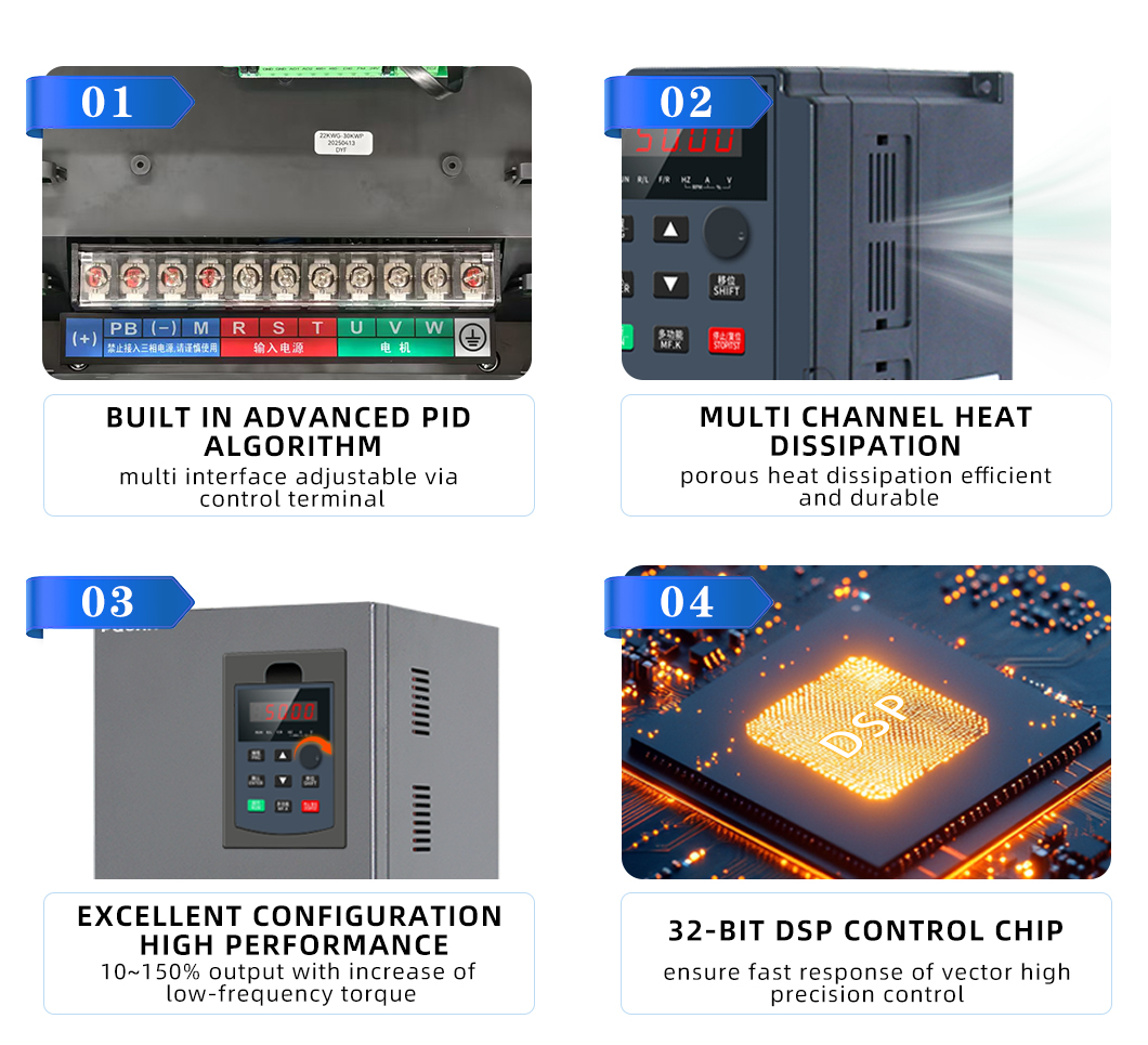
| Control Mode | Open loop vector control,V/F control, torque control, PID | |
| Startup Torque | Open loop vector control:0.5Hz 180%, V/F control:0.5Hz 150% | |
| Speed adjustableRange | Open loop vector control 1:200, V/F control: 1:100 | |
| Steady-state Speed Accuracy | Open loop vector control ±0.2%, V/F control ±0.5% | |
| Torque Control Accuracy | ±5%(SVC) | |
| Overload Capability | G type: 150% rated current 60s,180% rated current 3s | |
| P type: 120% rated current 60s,150% rated current 3s | ||
| Torque Boost | Automatic Torque Boost, Manual Torque Boost 0.1%~30.0% | |
| V/F Curve | Line Type、Multi-point Type, N-power V/F curve | |
| Ramp mode | Straight-line ramp; S-curve ramp; | |
| Four groups of acceleration/deceleration time with the range of 0.0 to 3200.0s. | ||
| DC Brake | DC Brake Frequency:0.00Hz to maximum frequency. | |
| Brake time: 0.0s to 36.0s | ||
| Braking operation current value: 0.0%~100.0% | ||
| Simple PLC multi-speed operation | Realize up to 16-speed operation through built-in PLC or control terminal. | |
| Onboard PID | It realizes process-controlled closed loop control system easily. | |
| Automatic Voltage Regulator (AVR) | Automatically regulates the output voltage to maintain a constant level regardless of grid voltage fluctuations. | |
| Over-voltage/current Stall Control | The current and voltage are limited automatically during the running process so as to avoid frequent tripping due to overvoltage/over current. | |
| Fault current limiter | Protect the inverter by minimizing overcurrent conditions. | |
| Torque limiting and control | It can limit the torque automatically and prevent frequent over current tripping during the running process. | |
| Tailored options | Excellent performance | Implement motor control using advanced current vector control. |
| Fault-tolerant: | Regenerative braking during a power sag enables the inverter to sustain operation. | |
| Timing Control | Timing control function:set time range 0.0~3200.0Min | |
| Bus Support | RS-485:Modbus | |
| Running | Running Command Source | Operation panel/Control terminals/Serial communication port. You can perform switchover between these sources in various ways. |
| Frequency Source | Digital setting, analog voltage setting, analog current setting, pulse setting and serial communication port setting. | |
| Auxiliary frequency source | 10 kinds of auxiliary frequency sources. Flexible realization of auxiliary frequency fine-tuning and frequency synthesis. | |
| Control Signal Input Terminal | 6 digital input terminals, one of which supports up to 20 kHz high-speed pulse input. | |
| 2 analog input terminals, one of which only supports 0-10 V voltage input and the other supports 0-10 V voltage input or 4-20 mA current input. | ||
| Control Signal Output Terminal | 1 digital output terminal; | |
| 2 relay output terminal; | ||
| 2 analog output terminal that supports 0-20 mA current output or 0-10 V voltage output; | ||
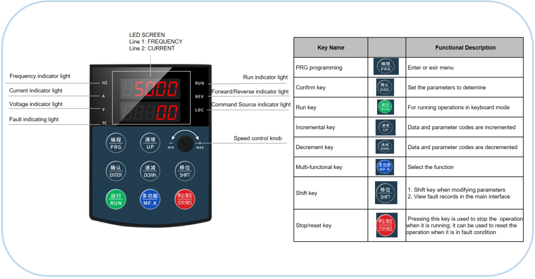
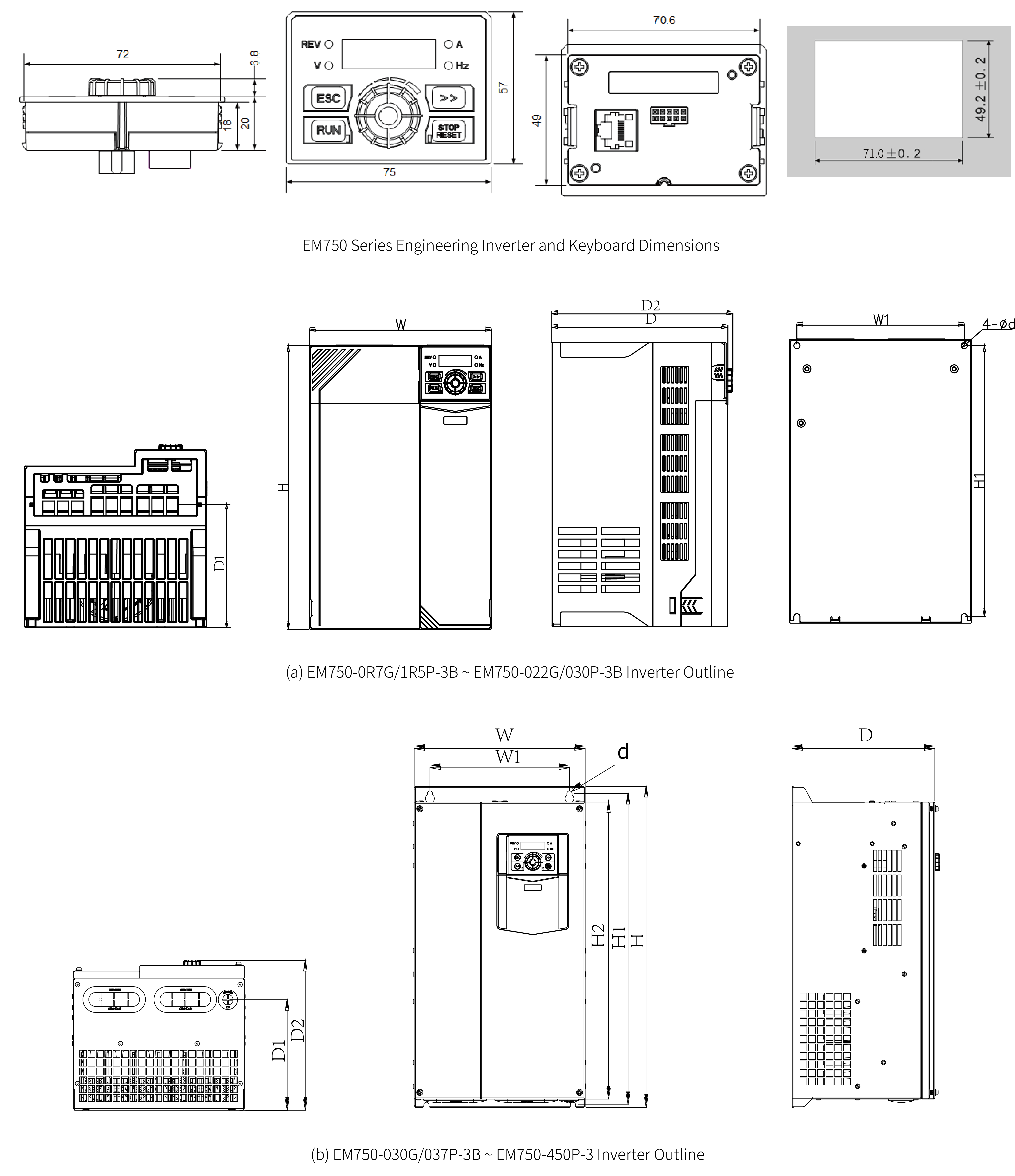
| Control panel | LED DISPLAY | Five-digit numerical readout |
| Key locking and function selection | It can lock the keys partially or completely and define the function range of some keys so as to prevent mis-function. | |
| 25 Protection Function | Motor short-circuit detection at power-on, input/output phase loss protection, over current protection, overvoltage protection, under voltage protection, overheat protection and overload protection. | |
| Environment | Installation environment | Inside, avoid direct sunlight, salt, dust, corrosive or flammable gas, smoke, steam. |
| Altitude | Below 1000 meters above sea level. (reduce the load level when used above 1000 meters above sea level) | |
| Ambient Temperature | -10 ℃ to +40 ℃ (Derating use when under ambient temperature of 40 ℃ to 50 ℃) | |
| Humidity | Less than 95%RH, without condensing | |
| Vibration | Less than 5.9m/s (0.6g) | |
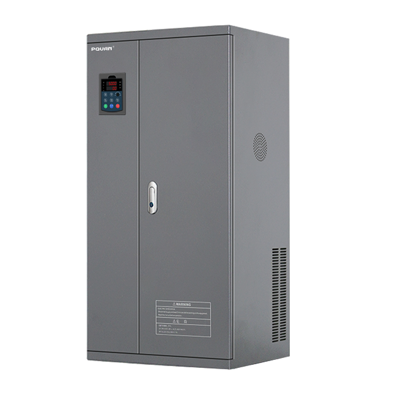
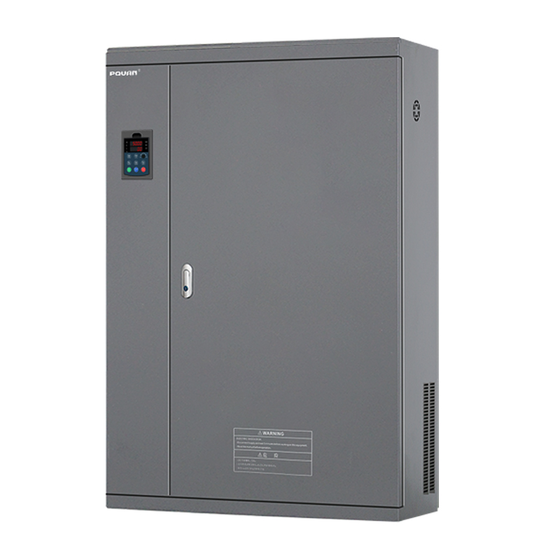
| Structure | Protection level | IP20 |
| Cooling method | Forced air cooling | |
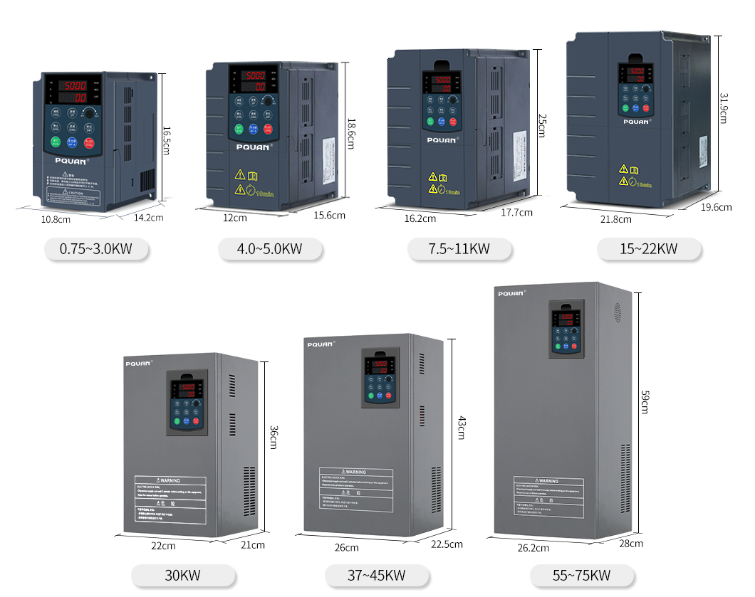
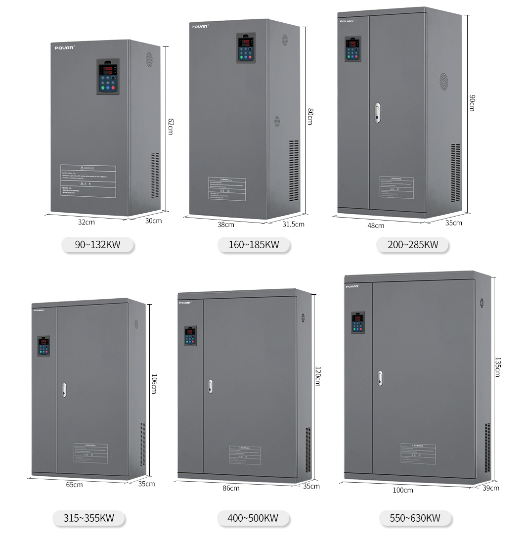
| Installation method | Wall-mounted, floor-standing electric control cabinet. | |


| Inverter Model | Power Capacity | Input Current | Output Current | Adaptive motor | Peripheral Dimension | Installation aperture | Facade | ||||
| KVA | A | A | KW | H | W | D | A | B | Φ | # | |
| Input:1Phase 220V±15%、50/60HZ Output: 3Phase 200~240V/ 380V(440V) | |||||||||||
| PQ580-R40G1B | 1 | 5.4 | 2.5 | 0.4 | 162 | 105 | 150 | 95 | 150 | 5Φ | FIG.1 |
| PQ580-R75G1B | 1.5 | 8.2 | 3.8 | 0.75 | |||||||
| PQ580-1R5G1B | 3 | 14 | 7 | 1.5 | |||||||
| PQ580-2R2G1B | 4 | 23 | 9 | 2.2 | |||||||
| Input :3Phase 220V±15%、50/60HZ, Output: 3Phase 200~240V/380V(440V) | |||||||||||
| PQ580-R40G2B | 1.5 | 3.4 | 2.5 | 0.4 | 162 | 105 | 150 | 95 | 150 | 5Φ | FIG.1 |
| PQ580-R75G2B | 3 | 5 | 3.8 | 0.75 | |||||||
| PQ580-1R5G2B | 4 | 5.8 | 7 | 1.5 | |||||||
| PQ580-2R2G2B | 5.9 | 10.5 | 9 | 2.2 | |||||||
| PQ580-3R0G2B | 7 | 14 | 13 | 3 | |||||||
| PQ580-3R7G2B | 8.9 | 18 | 17 | 3.7 | 186 | 119 | 165 | 107 | 175 | 5Φ | FIG.2 |
| PQ580-5R5G2B | 17 | 26 | 25 | 5.5 | |||||||
| PQ580-7R5G2B | 21 | 35 | 32 | 7.5 | 248 | 161 | 185 | 148 | 236 | 6Φ | FIG.3 |
| PQ580-011G2B | 30 | 46.5 | 45 | 11 | |||||||
| PQ580-015G2B | 40 | 62 | 60 | 15 | 320 | 220 | 205 | 205 | 305 | 6Φ | FIG.4 |
| PQ580-18R5G2B | 57 | 76 | 75 | 18.5 | |||||||
| PQ580-022G2 | 69 | 92 | 91 | 22 | |||||||
| PQ580-030G2 | 85 | 113 | 112 | 30 | 360 | 220 | 218 | 160 | 348 | 7Φ | FIG.5 |
| PQ580-037G2 | 114 | 157 | 150 | 37 | 430 | 260 | 225 | 180 | 412 | 7Φ | FIG.6 |
| PQ580-045G2 | 134 | 180 | 176 | 45 | |||||||
| PQ580-055G2 | 160 | 214 | 210 | 55 | 590 | 263 | 275 | 200 | 570 | 9Φ | FIG.7 |
| PQ580-075G2 | 231 | 307 | 304 | 75 | |||||||
| Input:3Phase 380V±15%、50/60HZ, Output: 3Phase 380V(440V) | |||||||||||
| PQ580-R75G/1R5P-4B | 1.5 | 3.4 | 2.1/3.8 | 0.75/1.5 | 162 | 105 | 150 | 95 | 150 | 5Φ | FIG.1 |
| PQ580-1R5G/2R2P-4B | 3 | 5 | 3.8/5.1 | 1.5/2.2 | |||||||
| PQ580-2R2G/3R0P-4B | 4 | 5.8 | 5.1/7.0 | 2.2/3.0 | |||||||
| PQ580-3R0G/3R7P-4B | 4.5 | 9 | 7.0/9.0 | 3.0/3.7 | |||||||
| PQ580-3R7G/5R5P-4B | 5.9 | 10.5 | 9.0/13 | 3.7/5.5 | 186 | 119 | 165 | 107 | 175 | 5Φ | FIG.2 |
| PQ580-5R5G/7R5P-4B | 8.9 | 14.6 | 13/17 | 5.5/7.5 | |||||||
| PQ580-7R5G/011P-4B | 11 | 20.5 | 17/25 | 7.5/11 | 248 | 161 | 185 | 148 | 236 | 6Φ | FIG.3 |
| PQ580-011G/015P-4B | 17 | 26 | 25/32 | 11.0/15.0 | |||||||
| PQ580-015G/18R5P-4B | 21 | 35 | 32/37 | 15/18.5 | 320 | 220 | 205 | 205 | 305 | 6Φ | FIG.4 |
| PQ580-18R5G/022P-4B | 24 | 38.5 | 37/45 | 18.5/22 | |||||||
| PQ580-022G/030P-4B | 30 | 46.5 | 45/60 | 22/30 | |||||||
| PQ580-030G/037P-4B | 40 | 62 | 60/75 | 30/37 | 360 | 220 | 218 | 160 | 348 | 7Φ | FIG.5 |
| PQ580-037G/045P-4 | 57 | 76 | 75/91 | 37/45 | 430 | 260 | 225 | 180 | 412 | 7Φ | FIG.6 |
| PQ580-045G/055P-4 | 69 | 92 | 91/112 | 45/55 | |||||||
| PQ580-055G/075P-4 | 85 | 113 | 112/150 | 55/75 | 590 | 263 | 275 | 200 | 570 | 9Φ | FIG.7 |
| PQ580-075G/090P-4 | 114 | 157 | 150/176 | 75/90 | |||||||
| PQ580-090G/110P-4 | 134 | 180 | 176/210 | 90/110 | 620 | 320 | 300 | 260 | 600 | 9Φ | FIG.8 |
| PQ580-110G/132P-4 | 160 | 214 | 210/253 | 110/132 | |||||||
| PQ580-132G/160P-4 | 192 | 256 | 253/304 | 132/160 | |||||||
| PQ580-160G/185P-4 | 231 | 307 | 304/334 | 160/185 | 800 | 380 | 315 | 260 | 780 | 10Φ | FIG.9 |
| PQ580-185G/200P-4 | 270 | 350 | 334/377 | 185/200 | |||||||
| PQ580-200G/220P-4 | 290 | 385 | 377/426 | 200/220 | 900 | 480 | 350 | 360 | 876 | 10Φ | FIG.10 |
| PQ580-220G/250P-4 | 310 | 430 | 426/465 | 220/250 | |||||||
| PQ580-250G/280P-4 | 355 | 468 | 465/520 | 250/280 | |||||||
| PQ580-280G/315P-4 | 396 | 525 | 520/585 | 280/315 | |||||||
| PQ580-315G/355P-4 | 445 | 590 | 585/650 | 315/355 | 1060 | 650 | 360 | 500 | 1036 | 12Φ | FIG.11 |
| PQ580-355G/400P-4 | 500 | 665 | 650/725 | 355/400 | |||||||
| PQ580-400G/450P-4 | 600 | 785 | 725/820 | 400/450 | 1200 | 860 | 380 | 640 | 1173 | Φ14 | FIG.12 |
| PQ580-450G/500P-4 | 700 | 883 | 820/900 | 450/500 | |||||||
| PQ580-500G/550P-4 | 800 | 1000 | 900/980 | 500/550 | |||||||
| PQ580-550G/630P-4 | 900 | 1100 | 980/110 | 550/630 | |||||||
| PQ580-630G/700P-4 | 1000 | 1200 | 1100/1200 | 630/700 | 1350 | 1000 | 390 | 800 | 1315 | Φ14 | FIG.13 |
Please contact our professional technical engineers, We will do our best to serve you
Scan the code to get more information